
Testing & Engineering
Utilizing our 35+ years of engineering and marketing experience in optoelectronics, Marktech’s customization process focuses on customer needs and applications. Instead of using standardized–but perhaps non-optimized–parts, Marktech allows advantageous custom product variations to enhance your product design needs. Marktech Optoelectronics has solved challenging LED design, assembly and manufacturing problems for a wide range of customers. Marktech’s company size and market focus allows it to offer customized variations of products that are not available from typical optoelectronic suppliers.
Resources are provided for component selection, packaging options, testing and expert advice, providing the designer with insights concerning custom variations that can be leveraged to optimize electrical, optical, and thermal characteristics–without the need for large volume commitments.
Design
Marktech has the design and test expertise you need to get your product to market faster, working with you every step of the way from prototype testing to high volume production.
What you can expect from working with Marktech:

Initially, our staff of experienced engineers will gain an understanding of your application and the environment in which it will be used.
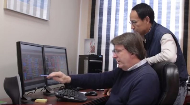
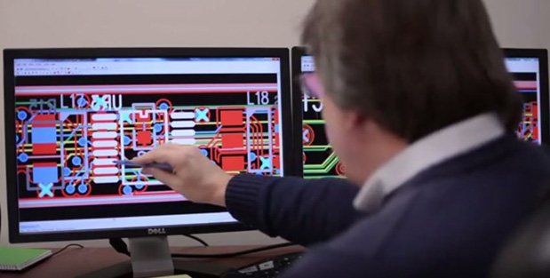
Next, using computer aided design, specialized software, and engineering tools, we operate within the parameters of your primary concept and specification documents to design and develop a product that meets your requirements.
Test Services
Once a prototype of your product is created, testing can begin in our onsite components lab. Testing is supported by a complete onsite components lab with measurement capability for validation of wavelength, angles, simulation of specific conditions, and full optical and electrical parametric characterization. Optical measurements can be obtained either “Photometrically” or “Radiometrically” as described below. Marktech’s application support also includes electrical parameter test, environmental test screening, and reliability testing for your specific needs.
Photometry
Photometry is simply the measurement of light in the visible spectrum (approximately 380nm-770nm). This is light seen by the naked eye of an average human observer. There are many different types of photometric units such as nits (cd/m2), lux (lumen/m2), footcandles (lumen/ft2), stilb (cd/cm2) etc. All of these are based on two basic photometric standards, the LUMEN and the CANDELA.
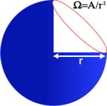
The Candela is the unit of luminous intensity, which can be defined as the amount of luminous flux (total luminous power emitted from a source and expressed as lumens) per unit solid angle in a given direction. The Lumen can be defined as the luminous flux emitted per unit solid angle from a uniform point source whose luminous intensity is 1 candela. (1 candela = 1 lumen/steradian) It is also important to understand the definition of steradian, which is the solid angle (cone) at the center of a sphere of radius “r” that subtends an area “r2” on the surface of the sphere. (See figure 1) The surface area of a sphere is 4Ï€ r2; therefore, a sphere has 4Ï€ steradians.
Figure1
Radiometry
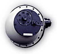
Radiometry refers to total radiation or the measurement of all light whether in the visible, infrared, or ultraviolet spectrum. The basic unit of radiometric optical power (Radiant Power) is the watt (W). The watt is an absolute unit because it is independent of wavelength. One watt of infrared light contains as much power as one watt of visible light. Other radiometric terms that are commonly measured are radiant intensity (Watts/Steradian), Irradiance (W/m2) and Radiance (W/m2 sr). The primary method for measuring total radiant power/luminous flux is by using an integrating sphere.(See figure 2 – 5)
The integrating sphere measures light emitted from the LED in all directions. Generally these measurements are independent of viewing angle and not subject to angular measurement inaccuracies seen when testing photometrically, however, errors are still possible. Sphere diameters of approximately 3 and 6 inches are widely used. If accuracy is critical, the larger diameter types are preferred due to the favorable ratio of the sphere area to the size of the LED and ports, however, this also results in a loss of intensity. A major source of measurement error has been where to position the LED inside the integrating sphere. The latest specification adopted by the CIE , Publication 127, states that the entire package of the LED should be inside the sphere which is called a 2 luminous flux measurement.
Integrating Sphere
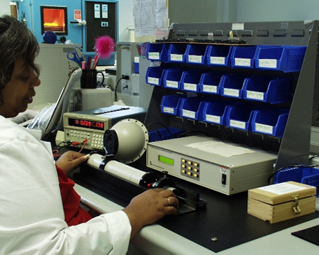
Figure 2 : Power output selection for 5mm red LED product
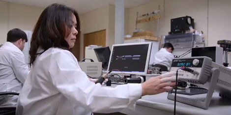
Figure 3: Optical parameter testing
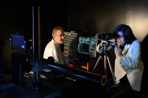
Figure 4: Photo Research combination Photometer/ Spectroradiometer equipment, utilized for spectrally based colorimetry and high speed, low level luminance testing
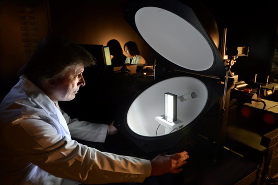
Figure 5: Light/power output characterization of finished custom devices
Reliability of LED Components and Assemblies
There are many factors that affect the reliability and lifetime of optoelectronic devices and assemblies. Marktech insures that all product designed, prototyped and manufactured undergoes rigorous testing and screening to insure optimal performance and life. Some of these conditions are outlined below.
Temperature Conditions of LEDs
It may be useful to calculate such information as the longevity characteristics (at high temperatures, normal temperatures, and low temperatures) of a discrete LEDs in an environment in which the equipment will be actually used, and to test those calculations by test operation of the equipment.
Humidity Conditions of LEDs
Depending on the material used in an LED, operating the LED under high-humidity, high-temperature conditions can dramatically reduce its lifetime. When an LED may be used under high-humidity, high-temperature conditions, be sure to check its longevity characteristics.
Current Conditions of LEDs
Because lattice defects increase with use, the luminous intensity of LEDs gradually declines. The speed of accumulation of lattice defects depends on the magnitude of the forward current.
Others Factors of LEDs
When using a LED under conditions where factors such as vibration, shock, gas, or ultra-violet affect the leads or resin, Marktech recommends testing the LED separately for each potential affecting factor.
LED Lamp Temperature Cycle Test
Temperature cycle testing is normally performed on the LED lamp structure at the upper-limit storage temperature and the lower-limit storage temperature.
Longevity Simulation
The following examples show how simulation can be used to obtain longevity information. For simplicity the characteristics of a hypothetical LED lamp are used. Example (a): Simulate the longevity of an LED lamp incorporated in control equipment installed in a room in which high-temperature equipment is operating.
Environment
High-temperature equipment operates for 1,080 hours a year (three hours a day x 360 days) with a forward current of 20 mA
LED lamp ambient temperature is 60°C, 60 days per year, humidity=”90%”
LED lamp ambient temperature is 40°C, 90 days per year, humidity=”90%”
LED lamp ambient temperature is 25°C, 210 days per year, humidity=”90%”
LED lamp longevity characteristics: Figure 6 shows the longevity characteristics of LED lamps.
REL Luminosity vs Time
Figure 6 – Simulation longevity characteristics
Simulation Example
Calculating the LED lamp operating time per year by ambient temperature.
Condition 1 operating time: 3 hours x 60 days = 180 hours
Condition 2 operating time: 3 hours x 90 days = 270 hours
Condition 3 operating time: 3 hours x 210 days = 630 hours
Figure 7 shows the results. In the example, the longevity characteristics are simulated by the approximate equation exp(-8 t), with 8 changing each time. Where the curve time constants for the characteristics in Figure 6 are 81, 82, 83 and luminosity reduction rate = exp (-8nt), the calculation is made by assigning 8 to each operating time.
Note: It is not possible to represent all the different longevity characteristics by a single approximate equation. It would be risky to extrapolate the characteristics over ten or 20 years based on the above examples and except the results to be accurate, even if the daily operating time were short. REL Luminosity Residue vs Time 1
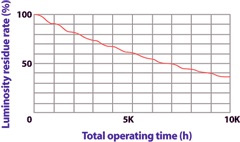
Figure 7 – Simulation example
Recent improvements have reduced the tendency for LED lamp luminosity to decline with use. The results of long-term studies of longevity characteristics now show that the luminosity need not always attenuate. The decline in luminosity that occurs during use has been evaluated using a Wiebel distribution function. Sometimes, even after thousands of hours of longevity testing, the M-value does not change thousands of hours (see Figure 8).
REL Luminosity Residue vs Time 2
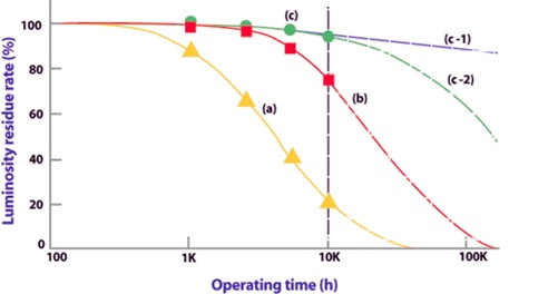
Figure 8 – Predictions from longevity test results (a), (b), (c)
With the tendency for luminosity to deteriorate already confirmed by the results of long-term longevity tests in Figure 8(a) and (b), longevity can now be predicted relatively easily. However, in Figure 8 (c), no deterioration is seen, even after 10,000 hours of use. It is not possible to decide whether deterioration proceeds in the (c-1) direction or the (c-2) direction. In some cases, the deterioration in the M-value is large after a certain point, as in (c-2).
The absence of luminosity reduction during longevity tests does not mean that the LED lamp will not deteriorate at some point in its life. When determining the location in which a piece of equipment incorporating an LED is to be used, if necessary perform longevity testing under accelerated conditions, so as to predict the longevity characteristics based on the actual conditions of use.
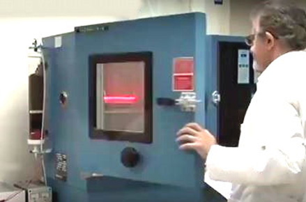
Tenney (Thermal Product Solutions) Temperature/ Humidity Test Chambers. Typically used for 85C/ 85% Relative Humidity rigorous environmental component life testing. Electrical bias testing is optionally included.
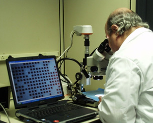
Quality inspection of bare dice on blue nitto (sticky) tape
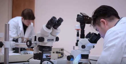
Visual product inspection and documentation
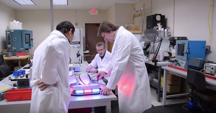
Team evaluation of custom product
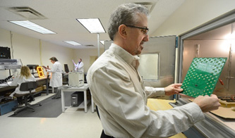
Quality inspection of a scoreboard product’s panel
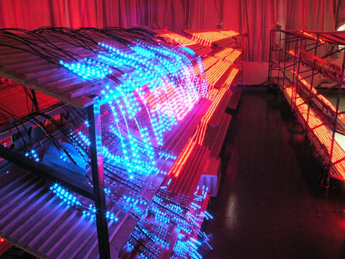
100% Burn-In of flexible strips for architectural lighting
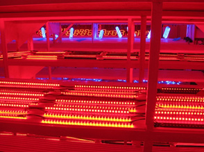
Burn In of flexible strip displays used for auto gas station pricing signage
Testing and Evaluation
By utilizing Marktech’s value-added engineering services, you will get a custom component or assembly that meets your unique specifications. We provide our customers with extensive testing and evaluation capabilities, ensuring your product is functioning exactly as expected.
Marktech’s testing and evaluation services include:
- Burn on
- IV / power output sorting
- Vf forward voltage / Vr reverse voltage testing
- Current gain sorting
- Wavelength sorting
- Angular measurements
- CCT and chromaticity coordinates
- Prototype capabilities
- Reliability testing
- Failure analysis
- Microscopic inspection
- Detector Spectral Response
- Detector efficiency
- Capacitance
- Dark Current
Machine Vision Lighting
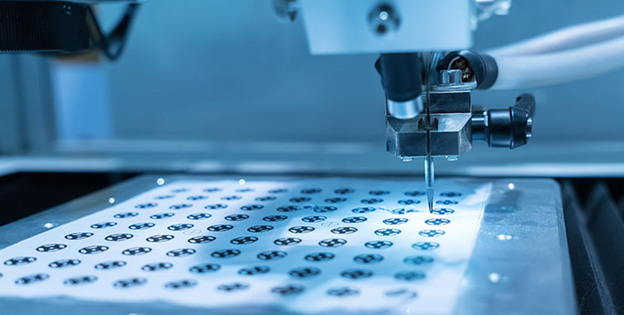
Marktech offers unique lighting solutions when it comes to machine vision lighting. To begin with we design our own printed circuit boards and specify the material composition since this is critical for proper die attach and wire bonding of the bare die. We also have the ability to sort +/- 1 nanometer on the die or luminosity and power output ratios of less than 2 to 1. Of great interest to our customer base is the fact that we can guarantee uniformity of light across large surface areas. Marktech can assist you in making the transition from thru-hole to chip on board. From initial concept through final product which includes the housing, Marktech can help take the stress out of achieving maximum lighting for your machine vision application.
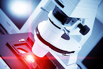
- State of the art designs incorporating chip on board
- Tight sorting options +/-1 nm
- Housing design and manufacturing
- High reliability
Proprietary advanced inspection equipment
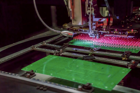
High speed LED insertion
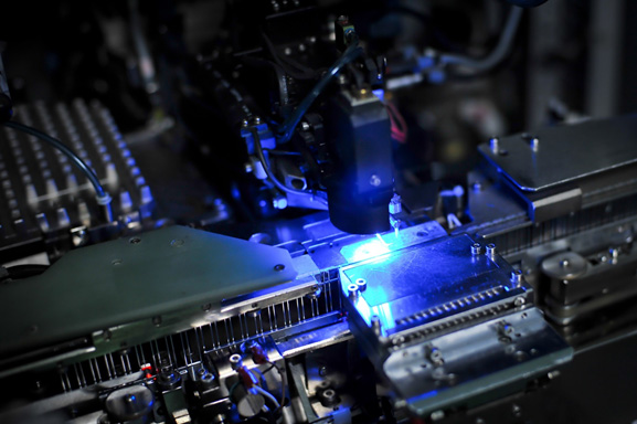
Machine vision inspection system
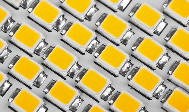
White LED strips and panels
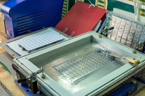
Star Board solder paste process
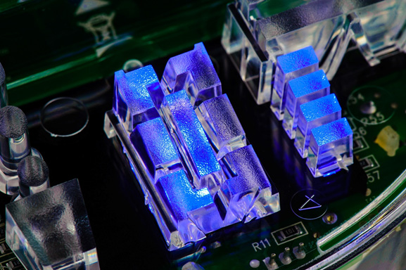
Customized optical package design
Customer service
Customer service is a top priority at Marktech. So, even after delivery, our team will stay in touch to make certain that your products are performing as expected.

View Products
Find something you were looking for? Get a free no-obligation quote today.
Related Resources
Have a question? Contact Us
The possibilities are limitless. Please contact us if you have a project requiring specialized optoelectronic testing of photodiode detectors, LED emitters, or both. Our detector and LED experts can help you understand optoelectronic device specifications, verify the performance of our or competitive devices, and troubleshoot detector or emitter problems. We can help with selecting the correct devices for your design requirements. We work on projects of any size and quantity, and while we have hundreds of standard products – customizations are our specialty.
