Precautions for Lead-Type Radial Taping
LED lamps are sold either loose or tape products. For mounting by hand, loose products are generally used, whereas tape products are required for automatic mounting. Toshiba has radial taping specifications are given in the Tape Specifications.
Precautions during Automatic Mounting
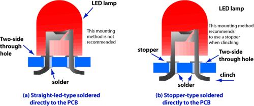
The following precautions should be observed during automatic mounting. LED lamps have a comparatively high lead strength compared to other radial tape electronic products and are classified as hard lead products. Therefore, when a number of LED lamps are being mounted, the life of the blade for cutting and clinching can be very short. Marktech therefore recommends that blades be checked for suitability and that mounting machine manufacturers install suitable blades. During automatic mounting, the cutting and clinching equipment vigorously pulls the LED lamp lead under the PCB. With straight lead LED lamps (as shown in Figure 10), this pulling applies stress to the LED lamp resin.

Figure 10 – LED lamp for automatic mounting machine (cross section)
To avoid this stress during automatic mounting, Marktech recommends using an LED lamp with a stopper or an LED in which the lead forming stress is not applied directly to the resin. Precautions when Cutting and Clinching Using Automatic Mounting Machine The following precaution should be observed when cutting and clinching with automatic mounting machine. Panasert, an insertion mounter for radial lead electronic component, is used as an example. Since the precaution vary according to the type of automatic mounting machine used, refer to the user manual for the mounting machine you are using when you check the following conditions. Marktech does not recommend settings for specific mounting machine. Anvil For the LED lamp automatic mounting machine, a two-lead anvil is suitable because of its movable blades. When using an anvil for three-lead devices, observe the following precautions. Align the strokes of the two movable blades for the LED lamp leads as closely as possible and avoid setting them so that the PCB is lifted by only one blade. As far as possible, adjust the timing of the moving blades so that they cut leads simultaneously; also, avoid setting the anvil in such a way that the center blade pulls the leads. Ensure that the blades are not chipped or worn, to avoid tearing the leads when cutting. Adequately test the mounting operation and set the anvil to avoid applying stress to the LEDs’ transparent resin. Designing the PCB hole diameter For some types of automatic mounting machine, there is a recommended lead insertion hole diameter for the PCB. However, the PCB has a through-hole pattern, the increase in the amount of solder necessary as a result of the increase in the diameter of the holes adversely affects the transparent resin. Also, as hole diameter increases, greater tension is needed to pull the lead when clinching. Therefore, test the mounting operation and set the hole diameter to an appropriate value. For single-sided PCBs, holes can be punched using a numerically controlled machine. When using a paper phenol PCB, avoid making the diameter of the hole too large (and avoid conically shaped holes).View Products
Find something you were looking for? Get a free no-obligation quote today.
